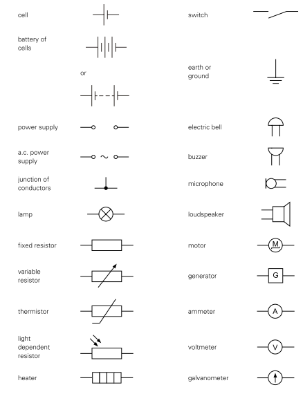
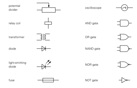
Circuit diagrams
All circuit components have a symbol.
Series and parallel circuits
Parallel circuits have multiple branching pathways for electrical current whereas a simple series circuit forms a single path.
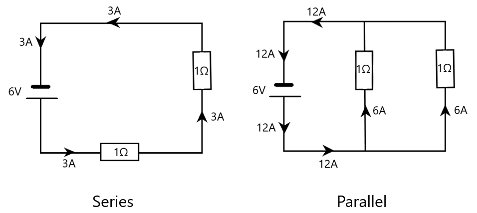
Make sure you pay attention to the numbers that I have labelled above.
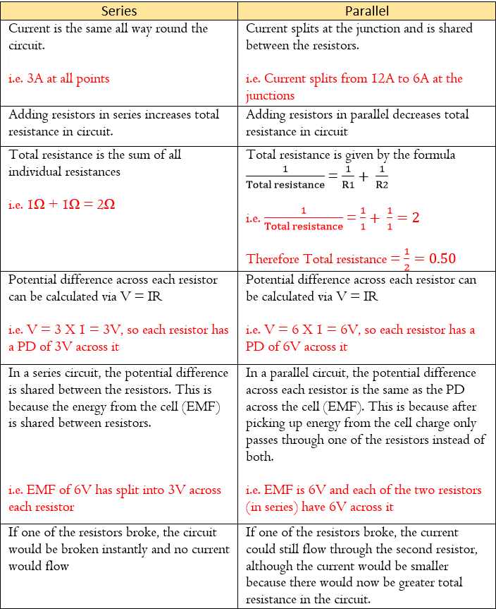
There are some important differences a circuit connected in series versus parallel.
Action and use of circuit components
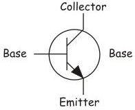
Transistor
A transistor is an electrically operated switch. It has three terminals: the base, collector, and emitter. When a small current enters the base, a larger current can flow between the collector and emitter. The transistor therefore amplifies the current.
Potentiometer
A potentiometer can give the circuit a certain level of control. For example, volume control is an example of this – As you raise the volume from minimum to maximum you are actually changing the voltage inside the circuit from low to high.
Fundamentally, a potentiometer can made from a variable resistor. A variable resistor works by adjusting the path that current has to flow. Take a look at the diagram below:
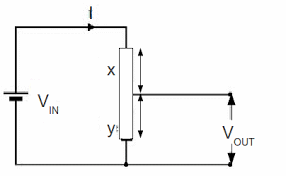
Imagine a resistor with a length of X+Y. Now let’s connect another wire that can SLIDE up or down the resistor. A voltmeter can be connected to measure the voltage (Vout) which is the voltage across the length Y of the resistor. Remember, the wire can SLIDE up or down. Sliding it up will increase the length Y and sliding it down will decrease the length Y.
Do you recall that in a wire, the longer it is the more the resistance? The same concept applies here. The longer length Y becomes, the more resistance there is. And recall that V=IR (voltage = resistance X current). The larger the resistance, the larger the voltage (Vout) will be!
Ultimately it means you can slide the moving wire along the resistor up or down to vary the RESISTANCE by varying the LENGTH at which the wire connects with the resistor.
- Sliding it up will INCREASE the resistance by INCREASING length Y which INCREASES the output voltage.
- Sliding it down will DECREASE the resistance by DECREASING length Y which DECREASES the output voltage
If this set up is connected to another component, for example an audio unit, then the variation of output voltage can determine the volume of the unit i.e. larger the output volume the larger the volume and vise versa.
Remember, the longer the wire the greater the resistance
Relays
A relay is an electrically operated switch. Many relays use an electromagnet to operate the switch.
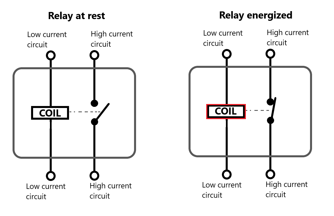
As electricity flows through the coil, it can “energize” the relay and it turns the coil into an electromagnet. The magnetic effect of this electromagnet “attracts” the open switch on the right and closes it to connect the circuit.
As you see in the diagram, a small current through the left circuit can be used to trigger the connection of the second circuit on the right which has a much higher current flowing through it. This is a major benefit of using relays.
Relays are quite commonly used with imput transducers such as thermistors and LEDs which we will be going through later. For now, be aware of the basics of how a relay works (which we’ve covered above).
Diode
A diode only allows one way flow of current through it (denoted by the arrow or direction of the triangle in the circuit diagram).
This property of the diode is used in the conversion of a.c. current to d.c. current.
This property of the diode is used in the conversion of a.c. current to d.c. current.
We touched on the subject of a.c. current and d.c. current on the topic of magnetizing & demagnetizing magnets. A.c. current is a type of current where the direction repeatedly changes. D.c. current on the other hand is unidirectional.
Since the diode only allows current to flow in one direction, it changes alternating current to direct current. This is called rectification.
A rectifier changes a.c. current into d.c. current. Therefore a diode can be used as a rectifier.
Input transducers
Transducers are devices that transform energy from one form to another. They are used in control systems, instrumentation, and electronic communications.
Input transducers are transducers that change non-electrical energy into electrical energy. There are two main input transducers that you need to know in your course:
- Thermistors
- Light dependent resistors (LDRs)
Thermistors

A thermistor’s resistance decreases as the temperature increases. For this reason, it is often used as a temperature sensor.
The diagram below demonstrates a temperature sensitive circuit:
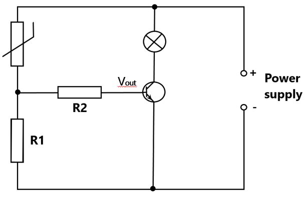
When the temperature rises, the resistance of the thermistor decreases. This means that it takes a smaller share of the potential difference from the power supply whilst R1 takes a larger share. The PD across the base (of transistor) is now large enough to switch on the collector-emitter current. When a large current flows from the collector to the emitter, the bulb begins to light.
This circuit can be used to turn on a temperature warning light for electric devices such as cookers, hair straighteners etc. When the temperature hits a certain level, the bulb begins to light.
Light dependent resistor (LDR)
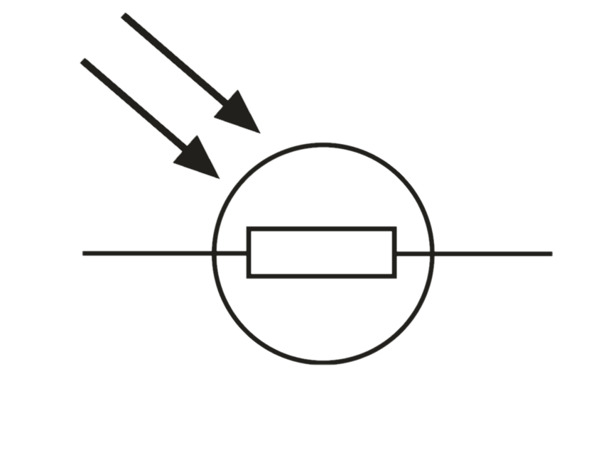
The light dependent resistor (LDR) has a resistance that decreases as light intensity increases (similar to a thermistor). This means that it can be used as a light sensor.
The diagram below demonstrates a light sensitive circuit:
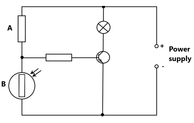
When the light intensity decreases, the resistance increases allowing the LDR (B) to take a larger share of the PD form the power supply. This also means that the resistor (A) takes a smaller share of the PD. The PD across the base is now large enough for the base current to switch on the collector-emitter current. When a large current flows from the collector to the emitter, the bulb lights.