Digital electronics
A digital system includes an input sensor and a processor circuit, which controls the voltage to an output device.
The processor circuit consists of a series of logic gates. Logic gates respond to small voltages which are either on or off. They do not respond to analogue signals.
- An analogue signal (V) varies continuously in amplitude
- A digital signal (V) has only two states: High or low (or on and off, or 1 and 0)
Logic gates
Logic gates transform a digital input voltage into an output, which depends on the type of logic gate.
The input voltages are given as 1 or 0 (on or off) and the input/output of these logic gates can be represented on a truth table.
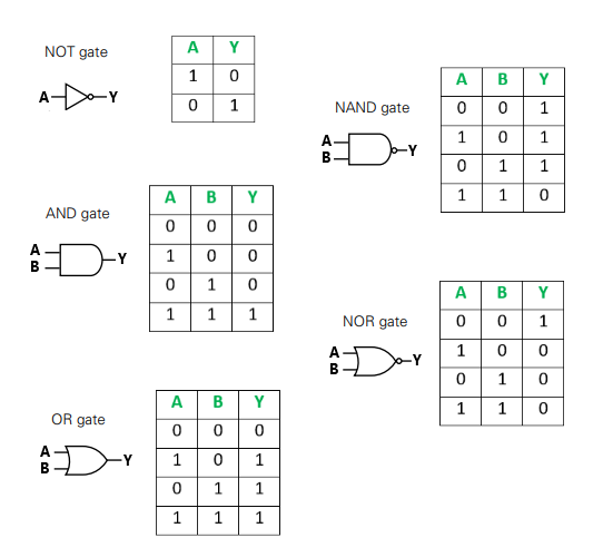
- A NOT gate gives an output that is opposite of the input
- An AND gate only gives an output if the input A and B are both 1
- An OR gate gives an output if input A or input B is 1
Logic gates can be combined to perform different functions in various electric circuits.